Miejsce pochodzenia: | CHINY |
---|---|
Nazwa handlowa: | TeXin |
Orzecznictwo: | SGS,ISO9001 |
Numer modelu: | TX-CD100W |
Minimalne zamówienie: | 1 |
Cena: | negocjowalne |
Szczegóły pakowania: | Trwała obudowa lub pudełko |
Czas dostawy: | 3-5 dni |
Zasady płatności: | L/C, D/A, D/P, T/T, Western Union, Moneygram |
Możliwość Supply: | 50,00 SZT/Miesiąc |
Częstotliwość: | 2000-7200 MHz (dostosowane) | Napięcie testowe: | 28-32v |
---|---|---|---|
Aktualny: | 9A | Wyjście: | 100W |
Osiągać: | 53 dBm | Stabilność wyjściowa: | 1dB |
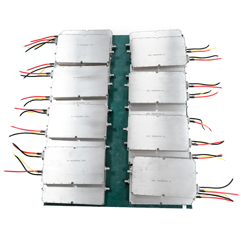
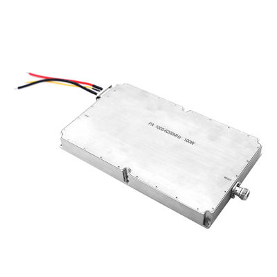
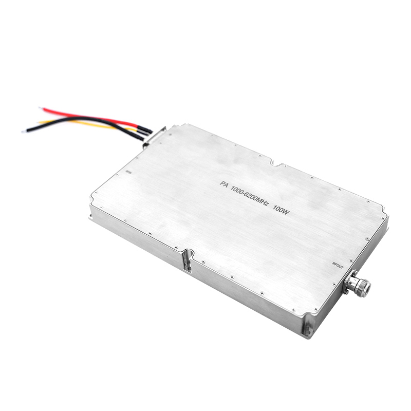
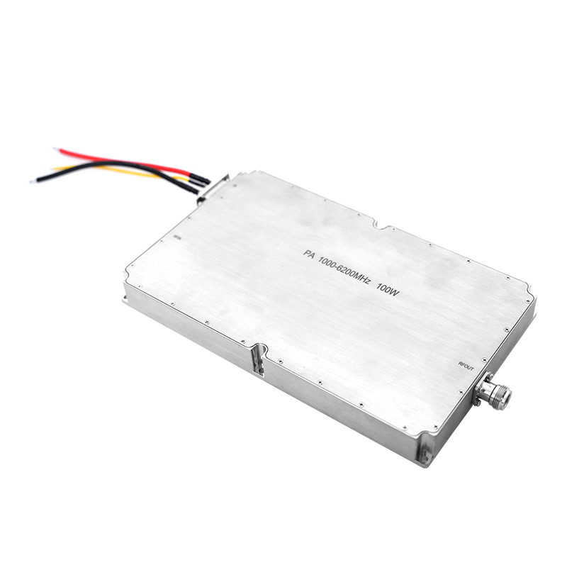
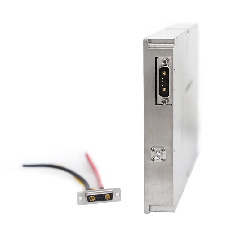
Złącze: | N/ Kobieta | Rozmiar skorupy zewnętrznej: | 220*110*26 mm |
Waga: | 1316g | Temperatura pracy: | -40~+65 |
Materiał powłoki zewnętrznej: | Aluminium | Aplikacja: | Zakłócacz dronów |
Podkreślić: | RF amplifier module 100W,drone jammer power amplifier,Ultra band amplifier 2000-7200MHz |
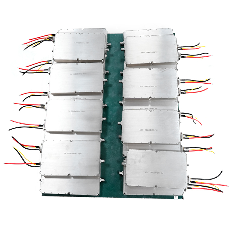
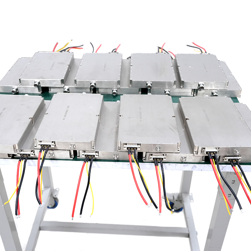
Professional Ultra band 2000-7200mhz 100W power amplifier module designed by Texin, it is ultra band range 2000-7200mhz in one module. Users can install it by themselves to interfere with drones in the range from a distance, and the band 2000-7200mhz 100W power amplifier module supports customization.
The wide band power amplifier jammer module can be applied in areas with high requirements for low-altitude safety, such as airports, military restricted areas, large-scale event venues, chemical parks, and nuclear power plants. For example, at airports, it can prevent drones from entering no-fly zones, ensuring the normal takeoff and landing of flights; at large event venues, it can prevent illegal drone filming, maintaining safety and order at events.
Description | Symbol | Min | Typ | Max | Unit | Remark |
---|---|---|---|---|---|---|
Operating Frequency | BW | 2000 | 7200 | MHz | ||
Input Power | Pin | 0 | dBm | |||
Output Power CW | Psat | 47 | 48 | 49.5 | dBm | Continuous Wave |
Power Gain | Gp | 48 | dBm | @ Pin=0 dBm | ||
Power Gain Flatness | △Gp | ±1.5 | dB | @ Pin=0 dBm | ||
Input Return Loss | S11 | -15 | dB | |||
Operating Voltage | Vdc | 28 | 28 | 36 | V | |
Current Consumption | A | 7 | 9 | A | @ Pout=50~85W | |
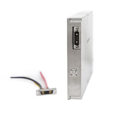
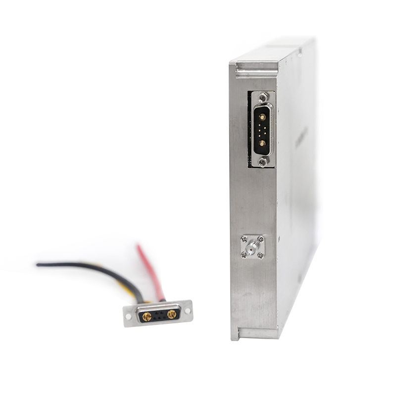
RF Connector Input | SMA, Female | |||||
RF Connector Output | SMA, Female | |||||
Max Input Power | PinMax | ≤10 dBm | ||||
Interface Definition | VDD | A1: 28Vdc | ||||
GND | A2: Ground | |||||
Enable | 1: 5V~Vdd:ON 0V:OFF |